

Interface and Application Programmg |
|
Individual Assignment :: |
|
|
To Write an application that interfaces a user with an input and/or output device that you have made
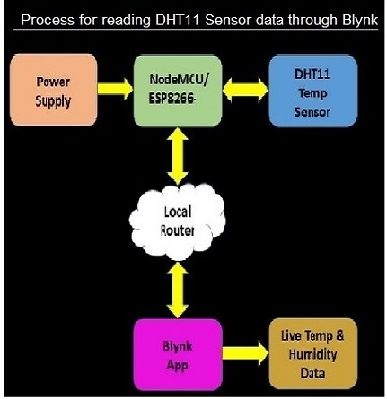
My final project results shows the live temperature and humidity of the surroundings and using ESP8266 Wi-Fi with DHT11 through the Blynk App. The sensors are used for measuring the temperatures from the surroundings, storing displayed information with different devices. Here, the ESP8266 Wi-Fi module has been used for data storing purpose. and also I have to do show the On/Off of lights and fans through Mobile App. So, in web and blynk so here i have Created a web interface with NodeMCU ESP8266 and blynk app.
|
|
Blynk App :: |
|
Most popular Internet of Things platform with free Cloud, iOS and Android mobile apps, Web dashboard, and Machine Learning. The website is https://blynk.io/ |
|
Blynk Server :: |
|
Responsible for all the communications between the smartphone and hardware. You can use our Blynk Cloud or run your private Blynk server locally. It’s open-source, could easily handle thousands of devices and can even be launched on a Raspberry Pi. |
|
Blynk Libraries :: |
|
for all the popular hardware platforms - enable communication with the server and process all the incoming and outcoming commands. |
|
Blynk Server :: |
|
| responsible for all the communications between the smartphone and hardware. You can use our Blynk Cloud or run your private Blynk server locally. It’s open-source, could easily handle thousands of devices and can even be launched on a Raspberry Pi. |
|
Few Blynk App -Features |
|
Similar API & UI for all supported hardware & devices |
|
- Easy-to-use Widgets
|
|
 |
|
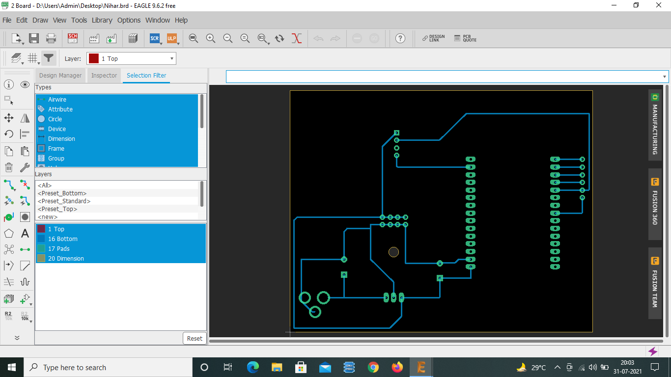
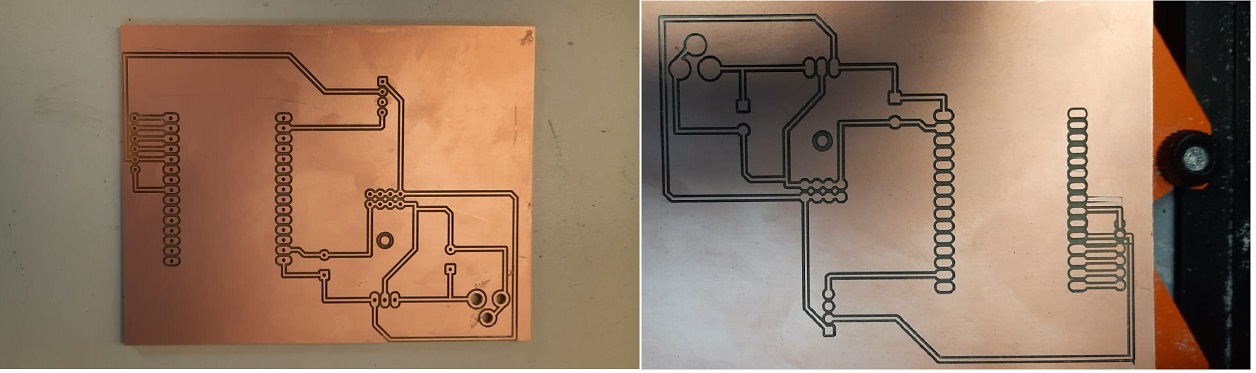
In my final project Smart Home Automation Device using IoT, I have designed PCB for nodemcu esp8266 with its input & output, I have integrated interfacing blynk and web in nodemcu esp8266 |
|
 |
|
 |
|
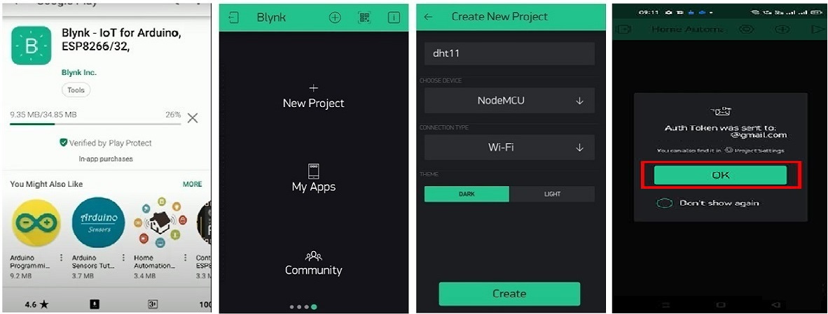
The best way to describe Blynk is that (internet of things) platform is designed to connect devices to internet using user-designed smartphone apps. Here I have tried explain briefly how I connected Blynk to control my system. BAsically for Connecting Arduino with a Blynk App requires 3 main steps: 1. Deigning Blynk app The first step is to create a new project in the Blynk App installed in my phone.
Simply by following these procedures, users will be able to create new project.: |
|
 |
|
|
INstallation and Configuration of Blynk App 1. First Download and install the “Blynk” app on your smartphone. 2. Create and Register an account for free by using your email. 3. CLick on New Project and enter the name of your new project as per your wish. I have selected as "Home Automation". Choose the device you want to be paired with in your project. I have named the device as "NodeMCU", Connection Type as "Wi-Fi" and then click "Create Icon". 4. After creating a new project, Blynk will send the Authorisation Token of your project to your email. This Authorisation Token will be used to pair your device to the Blynk project that you have created.This token is very important as it is required in the program/code. 5. If you didn’t receive the email, you can select the “Project Settings” and under “Devices” select the device that you are using for the Wifi module. 6. CLick on the "+" icon which located on top right side of the app to create buttons. 7. Enter the button name and select the GPIO pins to control the relays. Here I have named as D0, D1, D2, D3. Select the Mode as Switch for all the buttons. **Here I have used an active low Relay module, so to turn ON the relay we have to send “0” and “1” to turn OFF the relay. I have used virtual pins V1, V2, V3, V4 to control the first relay module (Room-1) And V5, V6, V7, V8 to control the second relay module (Room-2) |
|